

Laminated veneer lumber (LVL) and glue-laminated timber (glulam) products are designed for applications where they will be highly stressed under design loads. Drilling or notching of LVL and glulam should typically be avoided. However, in situations where it is not possible, these guidelines should be followed.
Glulam timber beams
Glulam beams are manufactured with lower-grade material in the mid-depth of the beam and higher-grade material positioned on the top and bottom. The highest grade of material is used as the outermost laminations on the tension side of the beam. Due to this, any drilling, dapping (countersinking), or notching taking place in these outermost tension laminations affects the strength and serviceability of the beam. First, such modifications reduce the section of the beam. Second, they remove wood fiber from the laminations having the highest strength. Additionally, stress concentrations may occur in areas modified by notching or drilling.
Prescriptive recommendations for field notching, tapering, and drilling glulam beams have been developed by the glulam industry based on a combination of practical experience and engineering analysis. These recommendations assume beams to be simple span, subjected to uniform loads and are shown with the compression side up. In typical timber construction, the floor or roof loads carried by the glulam beam are considered uniformly distributed unless significant loads are concentrated in a specific area, such as a column above or a beam-purlin hanger from a widely spaced purlin.
All equations and notching guidelines presented in this article use the same assumptions. If this information is applied to continuous or cantilevered beams, it should be used with extreme caution and only based on rational engineering analyses as notching or drilling continuous or cantilevered beams is more complex. It is important to understand improperly made field notches or holes may reduce the capacity of a properly designed member, possibly causing structural failure. The effects of any field notching or drilling should be checked by a designer competent in engineered timber design.
Notching
Notching of glulam members subject to transverse bending should be avoided whenever possible, especially on the tension side. Tension-side notching of glulam beams is not permitted except at end bearings, and then only under specific conditions. The notching of a bending member on the tension side results in a decrease in strength caused by stress concentrations developing around the notch, as well as a reduction of the area resisting the bending and shear forces. Such notches induce perpendicular-to-grain tension stresses, which, in conjunction with horizontal shear forces, can cause splitting along the grain, typically starting at the inside corner of the notch. Stress concentrations due to notches can be reduced by using a gradually tapered notch configuration in lieu of a square-cornered notch. Rounding the square corner of a notch with a radius of approximately 13 mm (0.5 in.) is also recommended to reduce stress concentrations in these areas.
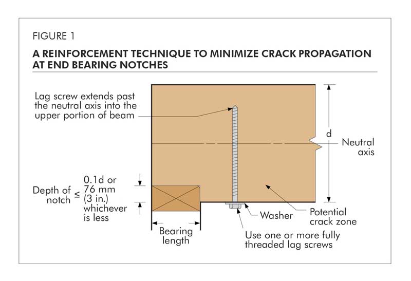
For square-cornered notches occurring at the ends of beams on the tension side, the designer may consider the use of reinforcement, such as full-threaded lag screws, to resist the tendency to split at the notch (Figure 1). Several design methodologies exist for sizing such screws. The design methodology selected and subsequent fabrication details are the responsibility of the designer/engineer of record. If lag screws are used, lead holes shall be predrilled in accordance with accepted practice. This procedure can also be used as a field remedy to minimize further propagation of an existing crack.
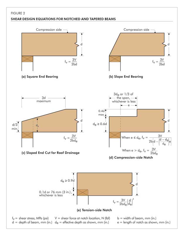
Where glulam members are notched at the ends for bearing over a support, the notch depth shall not exceed one-tenth of the beam depth. Figure 2(e) assists in evaluating the associated reductions to beam strength due to notching on the tension side. For notches on the compression side, a less severe condition exists and equations for the analysis of the effects of these notches are also given in Figure 2. The equations given are empirical in nature and were developed for the conditions shown.
As this guideline is limited to single span, simply supported beams, the notches shown in Figure 2 occur in areas of high shear and effectively zero moment. For this reason, the design equations given are shear equations. In situations where compression side notches extend into areas of significant moment, bending capacity of the beam should also be checked using the remaining section of the beam and the appropriate allowable stresses for those laminations left at the notch location.
When it becomes necessary to cut a small notch in the top of a glulam (in the compression zone) to provide passage for a small-diameter pipe or conduit, this cut should be made in areas of the beam stressed to less than 50 percent of the design bending stress. The net section in these areas should be checked for shear and bending stresses to ensure adequate performance.
All field notches should be accurately cut. Avoid over-cutting at the root of the notch. Drilling a pilot hole in the member at the interior corner location of a notch as a stopping point for the saw blade provides both a rounded corner and minimizes over-cutting at the corner.


What is your opinion of using 1/4 or 3/8 steel as a flitch plate bolted to 2x lumber in stead of lvl spans?