Crews dealt with less-than-ideal soil conditions and avoided the use of a mechanical bypass on a project that is improving the city of Fort Worth’s Sycamore Creek Sanitary Sewer Interceptor system, which has a current capacity of around 48 million gallons per day.
Several years ago, when the Sycamore Creek interceptor was having problems with sanitary sewer overflows, Lockwood, Andrews & Newnam Inc. (LAN) came on board to do some investigation and design point repairs at several locations to reduce inflow and infiltration and improve pipe conditions, explains Greg Vaughn, senior project manager with LAN.
“LAN determined what the capacity was going to be after those internal repairs were completed. Upon further investigation, it was discovered that after the repairs would be completed, the system would not be able to meet future flows for that interceptor basin,” he says. “Additionally, rehabilitation was going be expensive, especially considering the necessity of bypass pumping at these flow rates.”
LAN’s team was re-tasked with designing a parallel interceptor to handle the future capacity, including the ability to divert flow out of the existing interceptor so that rehabilitation of certain segments could be completed without wastewater bypass pumping, Vaughn says.
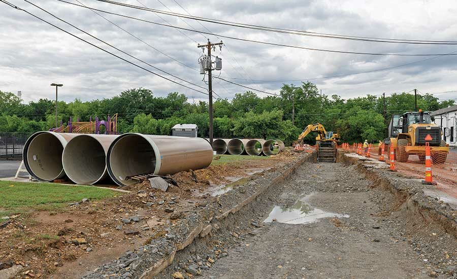
The Sycamore Interceptor program is a design-bid-build project that includes several phases of work, including cured-in-place pipe rehabilitation across 10 separate segments and construction of a 66-in.-dia parallel relief interceptor. Its capacity will be about 60 mgd, which, combined with the existing interceptor’s capacity, will be enough to handle the projected 79 mgd of needed capacity by 2030, Vaughn says.
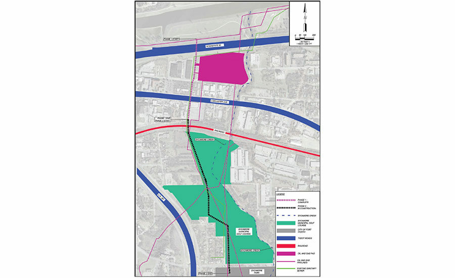
“The project was phased based upon the planned capital outlays by the city of Fort Worth over several budget years,” Vaughn says.
Phase 1 is reaching substantial completion, and construction on Phase 2 is just getting underway. Phase 3 is currently in design. The first three phases represent about $20 million in construction costs.
This work is also being done in response to the city of Fort Worth’s Interceptor Condition Assessment Program (ICAP), an effort that began in 2010 to inspect all the city’s major sewer interceptors, or pipes 24 in. dia or larger, using high-definition video, sonar and 3D lasers. The city then prioritized rehabilitation needs in order to meet the anticipated 2030 wastewater flows.
According to the city’s Water Department and Freese and Nichols, which collaborated on the ICAP program, at that point this was the largest-known implementation of this technology in the world. ICAP’s benefits thus far have been saving the city $6 million in cleaning costs and $26 million in reduced capital improvements, and has won numerous environmental and engineering awards.
Developing Solutions
The original 60-in.-dia reinforced concrete pipe (RCP) interceptor was installed in the early 1960s and was in rough shape before work began.
“Basically everything above the normal water level was starting to corrode. Everything below the water looked great, but everything else, especially near the bells and the spigots, was basically past its service life,” says Andy McCulloch, vice president with Phase 1 contractor Mountain Cascade of Texas LLC (MCTX).
Phase 1 includes 1,825 ft of 66-in.-dia pipe connecting to a 78-in.-dia downstream interceptor running perpendicular to the new interceptor along the Trinity River.
The first thing that the team had to work out was how to handle the existing sewer flows, McCulloch says. Also, the team had to deal with the potential necessity of bypass pumping for three to four months while the interconnecting junction box was being constructed, adds Vaughn.
“It was important to remove the wastewater flow from the existing interceptor during construction of the cast-in-place concrete box,” Vaughn says.
“If there’s potential to divert without running mechanical pumps, we’ll do it.”
– Andy McCulloch, Vice President, Mountain Cascade of Texas LLC
To avoid a mechanical bypass, MCTX devised, with approval from the city and LAN, a gravity bypass system. “We spent a lot of time and effort figuring out how to divert it rather than bypass it under generators, because we knew it was going to be diverted or bypassed for a long time, and knowing the propensity of generators and power to fail,” McCulloch says. “It’s something that we look at on every job; if there’s the potential to divert without running mechanical pumps, we’ll do it.”
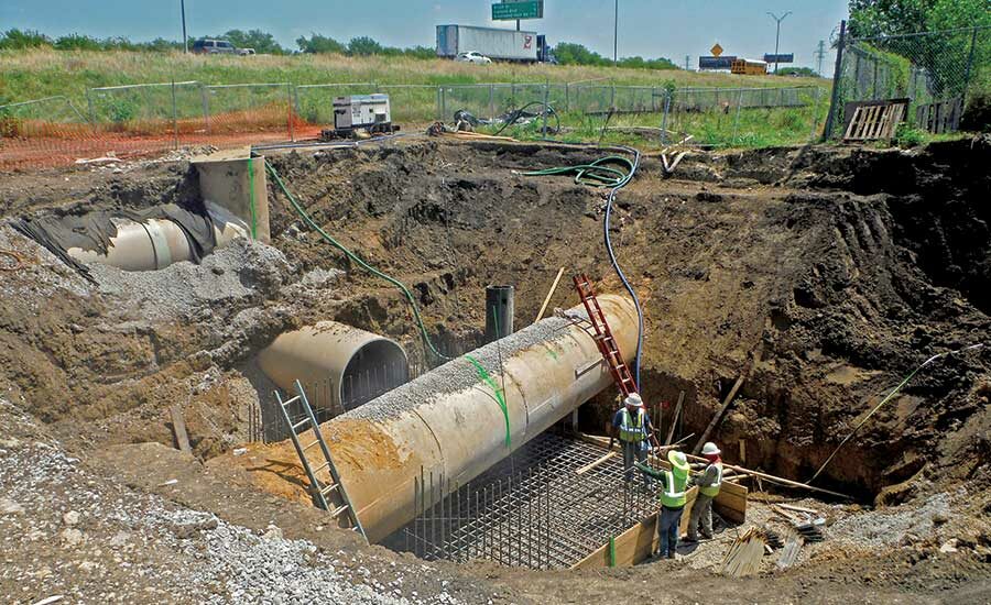
The gravity bypass consists of two permanent 5-ft polymer manholes with cast-in-place bases, approximately 200 linear ft of 60-in. fiberglass reinforced plastic (FRP) pipe and two pneumatic plugs. MCTX constructed the bypass to the existing 60-in. RCP line, then a cast-in-place base was built over the existing 60-in. line and bypass line at the connection point.
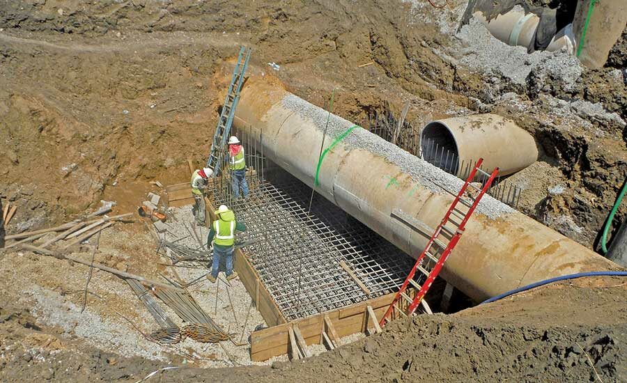
With the bypass in place, the contractor built the junction box without any wastewater bypass pumping, and no wastewater passed through the existing line, which was cast into the box, Vaughn says.
A gravity bypass was not originally part of the plans, and “the innovative portion of it was the partnering process. We had an idea, and LAN and the city were willing to listen and participate,” McCulloch says.
Meanwhile, the existing junction box connects to an existing 72-in.-dia concrete wastewater main and has a 60-in. concrete pipe stub-out, says Jason Williford, senior project manager with MCTX.
The new junction structure is approximately 18 ft 4 in. by 18 ft 4 in. and 19 ft deep, Williford says. It has 1-ft-8-in.-thick exterior walls, a 2-ft-4-in.-thick base slab and a 1-in.- by 3-in.-thick top slab. It connects to the new 66-in. FRP pipe on two sides and an existing 60-in. concrete pipe on two sides and houses four stop log assemblies that allow flows to be diverted into the new 66-in. FRP pipe or existing 60-in. concrete pipe downstream of the junction structure when installed, he says.
The new interconnecting junction box also happened to be on Texas Dept. of Transportation (TxDOT) right-of-way (ROW). Typically TxDOT doesn’t allow anything but a manhole on its ROW, but the team had to design a concrete structure that was exposed in the ROW for access purposes that would also withstand H-20 loads, Vaughn explains, in case a vehicle ended up on top of the junction box.
Polymer manholes were another fairly innovative choice. In the last decade or so, they have become more commonplace, but they’re still relatively new to the U.S., Williford says.
Current city requirements state that if precast or cast-in-place concrete manholes or junction boxes are used, that they have to have a corrosion-resistant coating installed, Vaughn says. This coating has to be installed at least 30 days after installation, which would cause commissioning delays.
So the team decided to go with polymer concrete manholes, manufactured by Armorock, since they’re corrosion resistant and don’t require a spray-on coating. In the past, polymer manholes were typically seen as too expensive an alternative, Vaughn notes. However, after bidding the first two phases, the project team determined that by the time it spent the extra money to get the polymer concrete manholes, the coordination and the wait time necessary to install a coated concrete manhole would actually be at higher cost than the polymer concrete manhole, he says.
“In Phase 1, costs for the polymer concrete option were approximately $1,000 higher. In the Phase 2 bid, they were approximately $1,000 cheaper. Therefore, we are seeing, especially on large-diameter interceptors, a move toward polymer concrete precast structures installed in the field,” he says. “Also, in Phase 2, all of our junction boxes are polymer concrete. We ended up doing unique shapes to get the size down small enough so the manufacturer could ship them.”
Since polymer manholes are corrosion resistant from the inside out, there’s no need to worry about nicking the coating, McCulloch adds. “I hope they take hold here in the Texas area. I believe they are,” he says.
Underground Tests
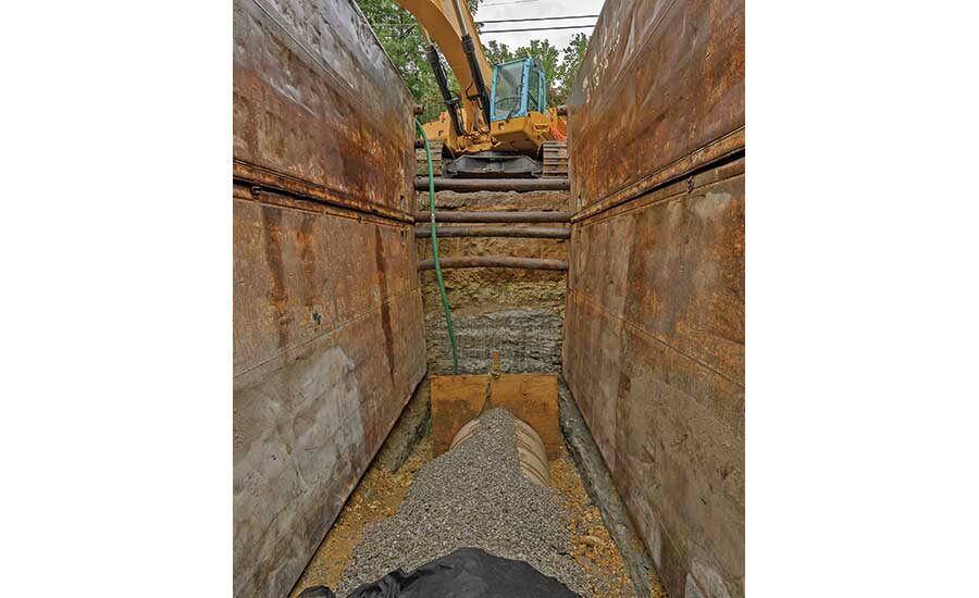
The interceptor required three tunnels, one of which was located underneath a multi-lane interstate, IH-30. Subcontractor LP Sundance Construction Inc. completed the tunneling work on the project. The other two tunnels passed under Bomar Avenue and East Lancaster Avenue, and each is 90 in. in diameter. The IH-30 tunnel is 373 linear ft, Bomar 65 linear ft and East Lancaster 156 linear ft, Williford says.
Each tunnel was hand-mined, given the possibility of a mixed face and unknown utilities in an urban area, he says. Difficult ground conditions added complexity.
“We knew the rock was going to be hard, and the groundwater came and went based on what was going on in the Trinity River to the north of us,” McCulloch says.
“We are seeing ... a move toward polymer concrete precast structures installed in the field.”
– Greg Vaughn, Senior Project Manager, Lockwood, Andrews & Newnam Inc.
During the first half of the project, groundwater was a constant. Approximately 6 in. to 12 in. of groundwater would be in the bottom of the tunnel every morning, which was removed using water pumps.
Approximately 10,000 cu yd of material was excavated during Phase 1. The soils were also subject to ground water influences, Vaughn explains.
“The soil would turn mushy once it was removed from its in-situ condition,” he says. “Those soil conditions required additional support before making the connection to that existing interceptor.”
The new interceptor was 18 ft deep on the downstream end, but the contractor found that at about 16 ft to 17 ft deep, there wasn’t enough good soil support material, Vaughn says. “Knowing that we were connecting into an existing line and meeting the tunnel alignment on the other side, we designed a manhole with a bigger footprint and 700 psi flowable fill from the support to a point 1 foot above the pipeline so it wouldn’t be influenced with the overburden soil material,” he explains. “To make sure the pipelines were properly supported, we designed the addition of flowable fill utilization around the pipe and manhole to a point above the water seepage level.”
To navigate around two high pressure steel gas lines, a 20 in. and a 10 in., at the connection point next to the Trinity River, the team chose to tunnel underneath. The design barely met the minimum requirement for separation under the 20-in. line, Vaughn says. Crews also discovered some inactive, abandoned underground lines.
The Phase 1 team has clocked approximately 10,800 worker hours, with zero lost time or injuries. During the project, a motorist did violate onsite traffic control and crashed into a loader, but walked away unharmed.
Phase 1 stops short of a railroad crossing upstream. Phase 2 contractor S J Louis will tackle tunneling underneath once permitting is finalized.
Phase 2 will include approximately 3,670 ft of 48-in., 54-in. and 66-in. FRP pipe, designed around a variety of large natural gas lines and overhead electric lines, existing sewer lines, water lines and a petroleum line, Vaughn says. “We designed different pipe sizes and slopes to maintain the desired interceptor capacity and allow us to get under certain gas lines and over others,” he says.


Post a comment to this article
Report Abusive Comment