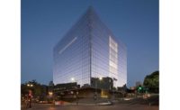
U.S. Courthouse—Los Angeles
Los Angeles
Region ENR California
Government/Public Building
Project Team
Owner U.S. General Services Administration
Lead Design Firm/Structural Engineer Skidmore, Owings & Merrill LLP
General Contractor Clark Construction Group
Civil Engineer Psomas
MEP Engineer Syska Hennessy Group Inc.
Concrete Subcontractor The Conco Cos.
Tasked with building a high-security, blast-resistant structure on a steep slope, the design-builders of Los Angeles’ U.S. Courthouse had nowhere to go but up. The cube-shaped building appears to float above public gardens but actually hangs from a 600-ton steel roof truss system supported by four reinforced-concrete cores.
The 627,000-sq-ft building’s profile also showcases its sustainable features, most obviously the 220,000-sq-ft pleated curtain wall that gives the courthouse a multifaceted appearance that changes throughout the day. The design-build project has received LEED Platinum status and includes a combined mechanical plant for cooling, heating and power.
The courthouse’s design began by drawing a simple square—the most efficient way to arrange four courtrooms on each floor with an atrium in the middle, says Craig Hartman, design partner at Skidmore, Owings & Merrill LLP. “We didn’t want it to look like a residential high-rise. A cube by itself was solid, balanced and civic in appearance.”
The glass-covered cube hovers above First Street, which runs downhill on a steep grade that drops nearly 30 ft across the front of the project site, Hartman says. Lifting the cube from the ground provided 36 ft more of setback from a protected perimeter on each side of the building to help meet federal government blast requirements. It also created new spaces for a civic plaza, public gardens and pedestrian walkways. The courthouse contains 24 courtrooms and 32 judges’ chambers and houses the U.S. District Court for the Central District of California.
For protected emergency egress, the building’s designers placed the four stairways inside the reinforced-concrete cores, says Eric Long, SOM director of structural engineering. This created four structures ideally placed to support a roof truss system. The cube itself essentially cantilevers from the concrete core with no perimeter support. The envelope of the cube is suspended from the roof trusses by steel “hanger” columns.
“Everyone thinks this courthouse is a steel structure, but from the basement up it acts as a concrete structure,” supporting the steel roof trusses,” says Brad McDermott, project executive with Clark Construction.
The 10-story, 220-ft-tall building also has four planar shear walls, which, along with the reinforced-concrete cores, resist lateral movement from earthquakes or high winds, eliminating the need for extra bracing and structural steel, McDermott says.
The project team incorporated the roof truss system into the building’s top floor, using the entire floor “sandwich” as a truss, Long says. “You get this giant tic-tac-toe board of trusses when you look down at the roof. They are aligned with the shear walls below and cantilever out to the building’s perimeter,” Long says. Despite the building’s ultimate top-down support system, workers built the cube from the bottom up, beginning with the structural steel, Long says. But the perimeter’s hanger columns couldn’t support themselves before the roof truss was completed. So the team installed a falsework system, incorporating 24 columns, each 42 in. in diameter and more than 50 ft tall.
Removing Shores Was a ‘Dance’
McDermott says they initially considered jacking the building up using the roof trusses. “Then we realized the truss is not in the right place to do the jacking—let’s do it through shoring.” The hanger columns were in compression during the construction process, McDermott adds. Once the roof truss system was completed, the team removed the supports, leaving the hanger columns suspended from the roof truss. “It was kind of a dance, removing first this one, then that,” he says. At that point, the hanger columns were in tension, and the entire cube systematically dropped 1.5 in.
Placing the reinforced concrete also was a challenge, since the steel part of the structure—including the floor decks—was already erected. The reinforcing bars needed to be threaded between the structural steel elements, so a super-plasticizer was added to the concrete. The design, engineering and construction teams met frequently early in the project to map the best routes for rebar placement.
“For most buildings, the higher up you go, the less rebar you need,” McDermott says. “We had rebar all the way to the top, since loads travel up the perimeter to the trusses.” The team developed a template of openings in the steel framing that could be used where other steel connections were embedded in the cores, McDermott says. The effort included building a full-sized timber mock-up with slotted holes for the rebar to slide through. “It was a way to keep the concrete [work] moving forward and staying right behind the steel structure as it was being erected,” he says.
In addition to its combined mechanical plant, the courthouse’s sustainable features include a 52,000-sq-ft, roof-mounted photovoltaic array. The electrical system includes two 5,000-amp substations and a 2,500-kW diesel generator for emergency power.
A key challenge was managing intense sunlight from the east and west. The team installed a pleated facade and transparent panels on the north and south sides to maximize daylighting, while opaque panels on the east and west sides reduce solar heat gain by nearly 50%. The building was prepared for a future biomass conversion so it can one day reach net-zero energy use.


Post a comment to this article
Report Abusive Comment