

The exterior façades of a multi-story office building in the southeastern United States had experienced water leakage since soon after construction 20 years ago. The exterior walls are principally clad with horizontal bands of aluminum framed curtain wall separated by brick masonry and architectural precast concrete (APC) spandrels, with some areas consisting of full-height brick masonry. During an investigation conducted to assess causes of water leakage, problems with the brick ties were discovered.
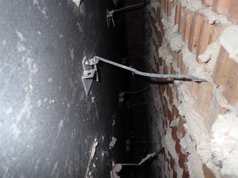
Inspection openings revealed the exterior wall cavity at the brick cladding varied from 76 mm (3 in.) to more than 178 mm (7 in.) deep from the interior face of the brick to the exterior face of sheathing on the metal stud-framed backup wall. Brick ties at the masonry wall areas consisted of adjustable two-piece anchor assemblies comprised of a sheet metal wall bracket and trapezoidal shaped wire tie with two downturned legs that engaged holes in the horizontal tabs of the bracket. To accommodate areas with a deeper wall cavity, the wire ties appeared to have been stretched into a single length of wire, with one end engaged in the bracket and the other end engaged in a bed joint of the brick cladding (rather than installing an adjustable anchor assembly more appropriately sized for this installation). At several locations, the wire was observed to be barely engaged in the bracket. At shallower wall cavities, while both vertical legs of the wire pintle were engaged in the wall bracket, the tie wire also appeared to have limited engagement into the brick.
TMS 402/602, Building Code Requirements and Specification for Masonry Structures, requires adjustable anchors be used to anchor brick veneer with a backing of cold-formed steel framing. When the cavity exceeds 117 mm (4.625 in.) depth, adjustable anchors should consist of two or more wires with a maximum allowable distance between the veneer and end of wire tie (where it bends at the bracket) of 50.8 mm (2 in.), to limit the potential for bending of the tie wire under load.
TMS 402/602 also limits the maximum distance between the inside face of the veneer and the cold-formed steel framing to 168 mm (6.625 in.) (for empirical design). It states that, when this distance is exceeded, the anchors for the veneer shall be designed using alternative (or rational) design procedures. The Brick Industry Association (BIA) Technical Note 44B recommends limiting the cavity to 114 mm (4.5 in.). TMS 402/602 also requires a minimum embedment into the brick cladding of 38 mm (1.5 in.) and does not allow wire ties with formed drips, as they can reduce the ultimate buckling load capacity of the tie by 50 percent; bending trapezoidal wire ties to stretch across the cavity is analogous to having multiple formed bends or drips in the wire tie. As constructed, the 178 mm deep cavity exceeds the code mandated maximum depth for empirical design of the lateral force resisting elements (anchors) for the brick cladding, and the single wire ties also do not meet code requirements.
To address deficiencies associated with the brick ties, as well as other conditions related to water leakage, the existing brick masonry will need to be removed and new brick cladding installed with anchorage meeting the requirements of TMS 402/602.
Deborah Slaton is an architectural conservator and principal with Wiss, Janney, Elstner Associates (WJE) in Northbrook, Illinois, specializing in historic preservation and materials conservation. She can be reached at dslaton@wje.com.
David S. Patterson, AIA, is an architect and senior principal with WJE’s office in Princeton, New Jersey. He specializes in investigation and repair of the building envelope. He can be reached at dpatterson@wje.com.
The opinions expressed in Failures are based on the authors’ experiences and do not necessarily reflect that of The Construction Specifier or CSI.

