

By Jacob W. Arnold, PE, Colin P. Rueb, PE, SE, and Kurt R. Hoigard, PE, SECB, F.ASTM
Since the early 20th century, fibrous cement sheets have been available for numerous construction applications. For many years, fibers in these cement sheets were primarily composed of asbestos. When the U.S. federal government passed its first legislation limiting the exposure of asbestos in the 1970s, manufacturers were forced to develop alternatives to asbestos-based fibers. By the late 1970s and early 1980s, production of asbestos-containing sheet products was discontinued by many manufacturers and replaced with fiber-cement products, where asbestos was replaced primarily by cellulose (i.e. wood), glass, or synthetic fibers.
In modern construction, fiber-cement products are frequently used in exterior cladding applications, as they provide a cost-effective solution for achieving the desired aesthetic for a project. In general, fiber-cement siding is relatively thin and lightweight, and manufacturers often describe their products as having excellent durability and weather-resistance.
In general, fiber-cement panels can be classified as composite panels comprised of sand and Portland cement, reinforced with cellulose fibers and other additives, which vary depending on manufacturer specifications. To manufacture fiber-cement panel products, components are processed and combined with water and mixed into a fiber-cement slurry. The water is then drained from the slurry using cylindrical sieves, creating a thin fiber-cement film. Residual water is removed from the film using a vacuum process, forming thin fiber-cement sheets that are then stacked and fused together into a single panel using a high-pressure roller. The panels are pressed smooth or incised with a specific pattern. The act of pressing the layers together tends to increase the stiffness and moisture resistance of the material. After the pressing operations, panels are oven-cured or autoclaved—a high-temperature, pressurized curing method. Panels are once again dried, cut to size, and finished with a factory-applied coating.
Common amongst the various manufacturers’ installation literature for fiber-cement panel siding products is the inclusion of requirements regarding the fastener head condition. In general, a fastener can be installed in one of three conditions:
• Proud, where the underside of the fastener head is seated on the face of the surface of the fiber-cement panel;
• Flush, where the top surface of the fastener head and the surrounding surface of the fiber-cement panel are even with each other; and
• Recessed, where the top surface of the fastener head is embedded below the surrounding surface of the fiber-cement panel.
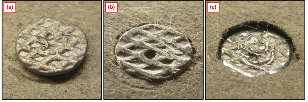
Figure 2 presents representative photographs of these three fastener head conditions. The fasteners in these photographs are nails.
Review of the various manufacturers’ product literature appears to indicate a “proud” fastener head condition is typically required. Language such as, “[the] head must be snug, not countersunk or overdriven,” or, “do not overdrive the nail,” appears in various installation instructions and technical bulletins.
Although manufacturers offer generally consistent fastener installation requirements, these requirements are frequently not followed in the field. The authors have observed numerous cases of fiber-cement panel installations with nail head conditions other than the required “proud” condition, including cases where the pull-through resistance of an installed fiber-cement siding product was of particular concern. This, in part, led to the development of a laboratory program to better understand the limit state behavior at fastener-to-panel interfaces.
Description and test program
Laboratory nail head pull-through testing was performed in general accordance with ASTM D1037, Standard Test Methods for Evaluating Properties of Wood-Base Fiber and Particle Panel Materials.
Fiber-cement panel products from three different manufacturers were included in the test program, as described in Table 1. Nominal thicknesses are presented in millimeters (mm) and inches (in.). Density values are presented in kilograms per cubic meter (kg/m3) and pounds per cubic foot (pcf). Products with similar thicknesses and densities were selected to provide the most direct comparisons possible. All three products are considered “medium-density,” according to product literature provided by the manufacturers. Manufacturer and product names have been purposely omitted.
Table 1 – Thickness and density of products included in the test program.
| Product
ID |
Thickness (mm) | Thickness (in.) | Density (kg/m3) |
Density
(pcf) |
| A | 7.9 | 0.31 | 1380 | 86 |
| B | 7.9 | 0.31 | 1310 | 82 |
| C | 6.4 | 0.25 | 1680 | 105 |
Test specimens were cut to a nominal size of 127 by 254 mm (5 by 10 in.). The fasteners used were selected to represent nails the authors have frequently observed at fiber-cement panel installations and were approximately 56-mm-long (2.19-in.-long) Round head coil siding nails with a nominal shaft diameter of 2.34 mm (0.09 in.), head diameter of 5.59 mm (0.22 in.), and head thickness of 0.51 mm (0.02 in.).

