Remove Architecture Remove Drawings Remove Fabrication Remove Structural Engineering
article thumbnail

More about design drawings and model planning

Construction Cost Estimating

Plans are like a set of drawings or two-dimensional diagrams that are used to narrate a place or object or to communicate building or fabrication instructions which are drawn or printed on paper and can take the form of a digital file. So these design drawings can be categorized as: • Feasibility studies. Concept drawings.

article thumbnail

BIM for Reinforced Concrete – From Design to Detailing in One Model

BIM & Beam

This is the third blog post in a series that discusses the advantages of working on concrete projects in a BIM process for structural engineers. Segmentation is dictated by engineering, architectural, or fabrication requirements, and its reinforcement is determined by the structural engineer.

professionals

Sign Up for our Newsletter

This site is protected by reCAPTCHA and the Google Privacy Policy and Terms of Service apply.

article thumbnail

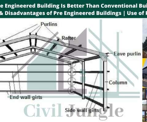
How Pre Engineered Building Is Better Than Conventional Building | Advantages & Disadvantages of Pre Engineered Buildings | Use of Pre Structure

CivilJungle

The pre-engineered buildings are widely used for the construction of industrial buildings and warehouses metro stations factories and bridges etc. PEB buildings are the steel structures which are fabricated at the factory to the required size and dimensions. PEB construction is economical and easier in fabrication.

article thumbnail

Rebar Projects in Revit

BIM & Beam

ABT Netherlands, a multi-disciplinary consultancy firm, focused on the structural engineering, civil engineering, architectural engineering, moved to BIM-based 3D rebar for concrete reinforced design and fabrication as a result of client demand.

Revit 40
article thumbnail

Revit 2017 - New Features and Enhancements

Revit OpEd

In Architectural and Coordination discipline views this allows you to apply a gradient override to make it more obvious which elements are farthest away compared to the elements that are closest to the cut plane of the view. Occlusion Culling (2016R2) - The Graphics tab in the Options dialog offers the new setting: Draw visible elements only.

Revit 40
article thumbnail

COMMON STRUCTURAL FAILURE CAUSES

The Constructor

The most common causes of structural failures are: (1) Poor communication between the various design professionals involved, e.g. engineers involved in conceptual design and those involved in the supervision of execution of works. (2) 2) poor communication between the fabricators and erectors. (3)

Concrete 177
article thumbnail

List of Common Construction Abbreviations

Job Order Contracting

ACF: Architectural Concrete Finish. ADAAG: Americans with Disabilities Act Architectural Guidelines. ARCH: Architect, Architectural. ASCE: American Society of Civil Engineers. ASME: American Society of Mechanical Engineers. DWG: Drawing. DWGS: Drawings. FAB: Fabricate. FABR: Fabricate.